|
|
|
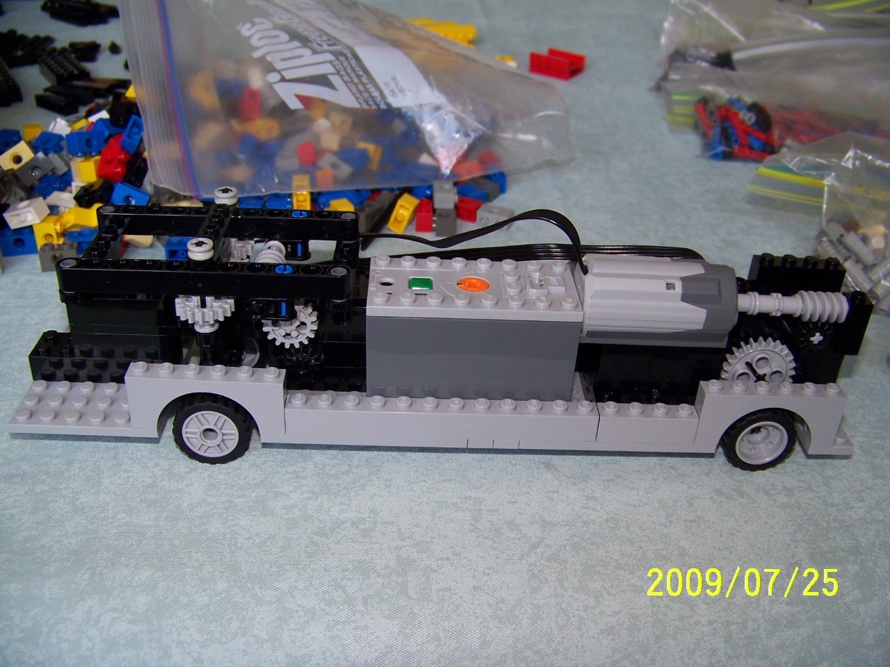
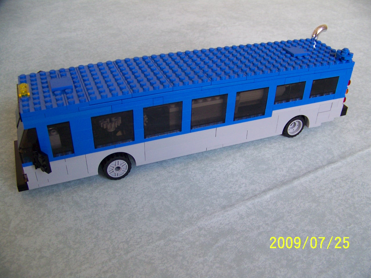
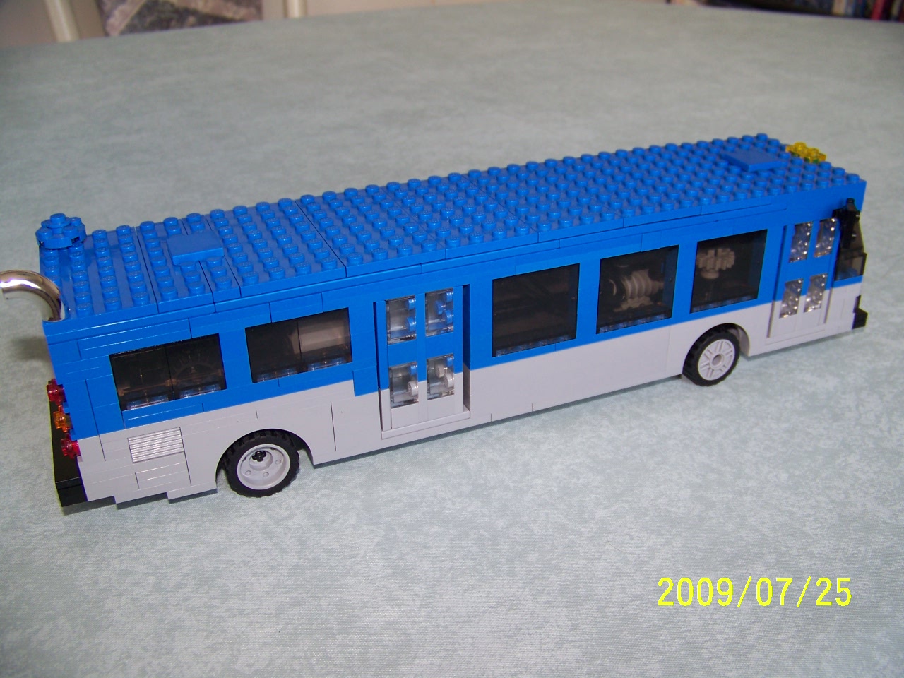
Several months after I had finished doing the ETS stuff, I received my "Emerald Night" train, and also my #8275 Power Functions bulldozer set. Those provided me with Power Functions parts, and some experience using them. At some point, I decided I should try to make my low floor bus (the only one still assembled) powered. The challenge was to do it without changing the appearance of the bus. The hard part would be the steering - there is not much room for movement inside those 1x6 arches. I succeeded in my challenge, but I did have to leave out the side number-board on the bus - it and the steering mechanism can't both be in that space.
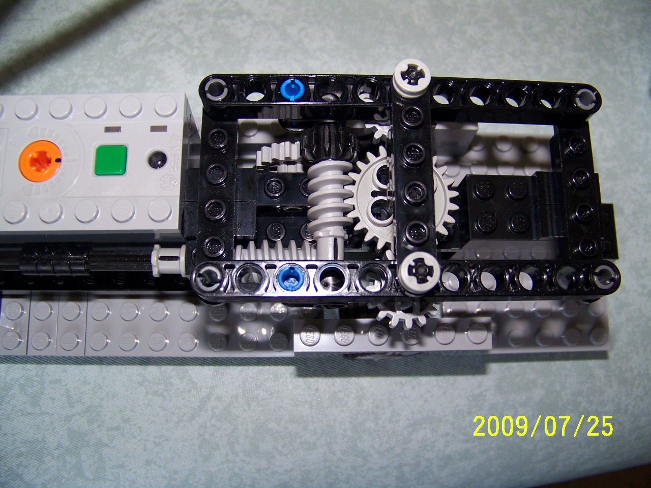
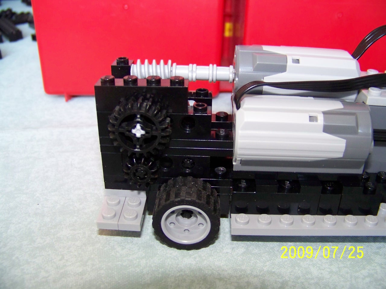
I went through two major and many minor versions of the steering mechanism. Getting anything that would work at all took quite a few hours of tinkering. Getting the rear wheels powered was much easier - a worm gear on the motor axle and an idler gear to get the correct spacing down to a gear on the rear axle. The first version, however, had speed problems - the bus crawled along slowly, and the steering moved too quickly.
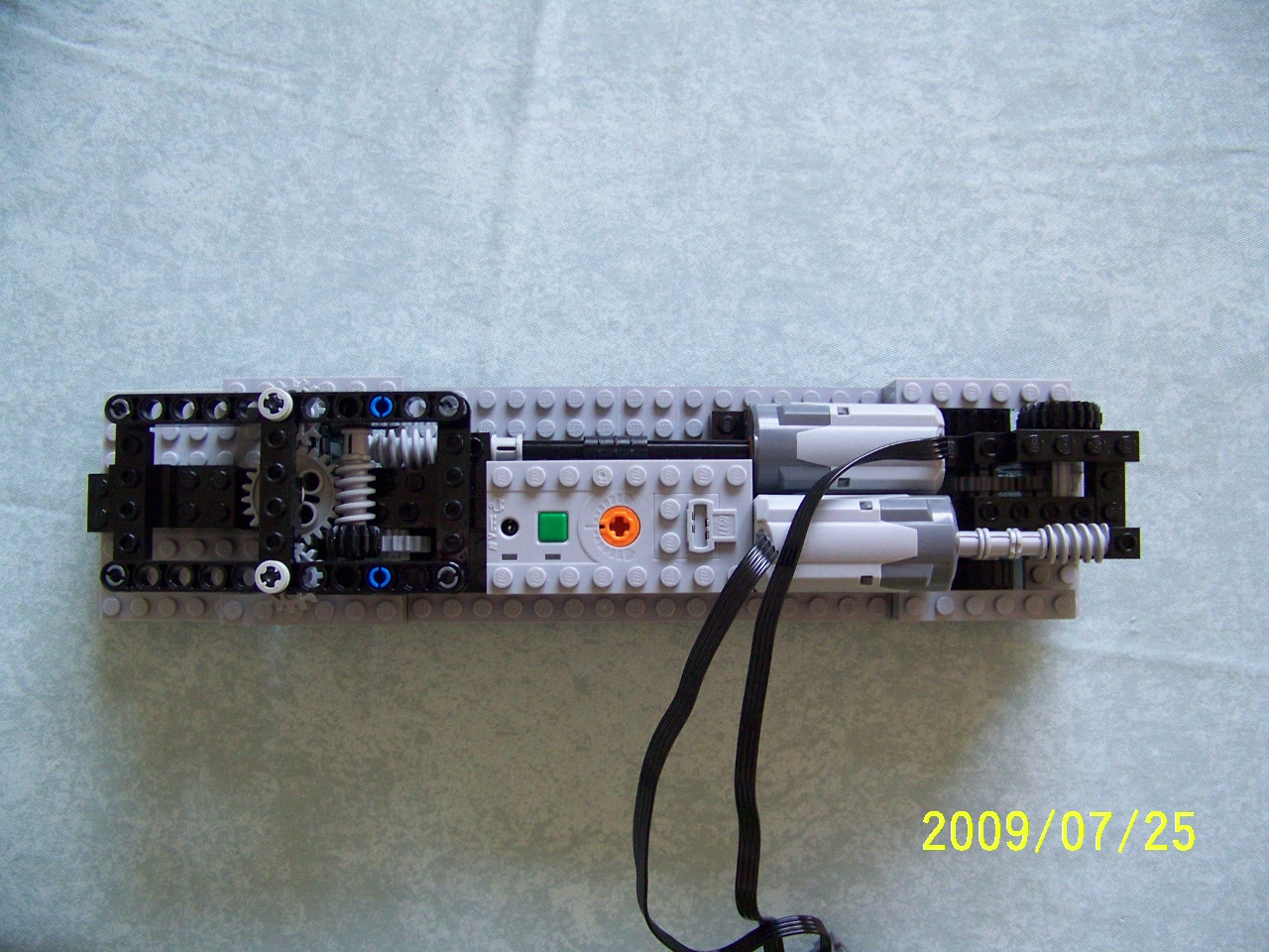
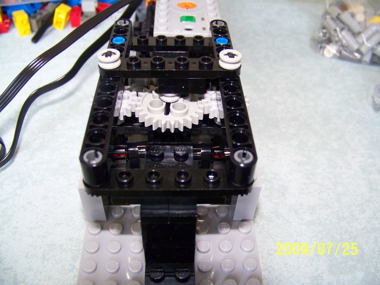
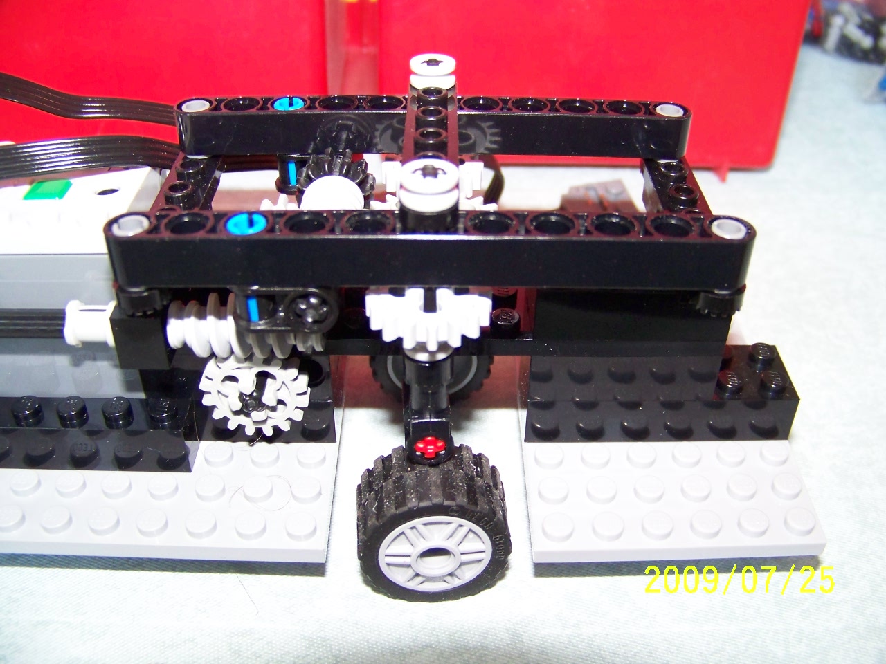
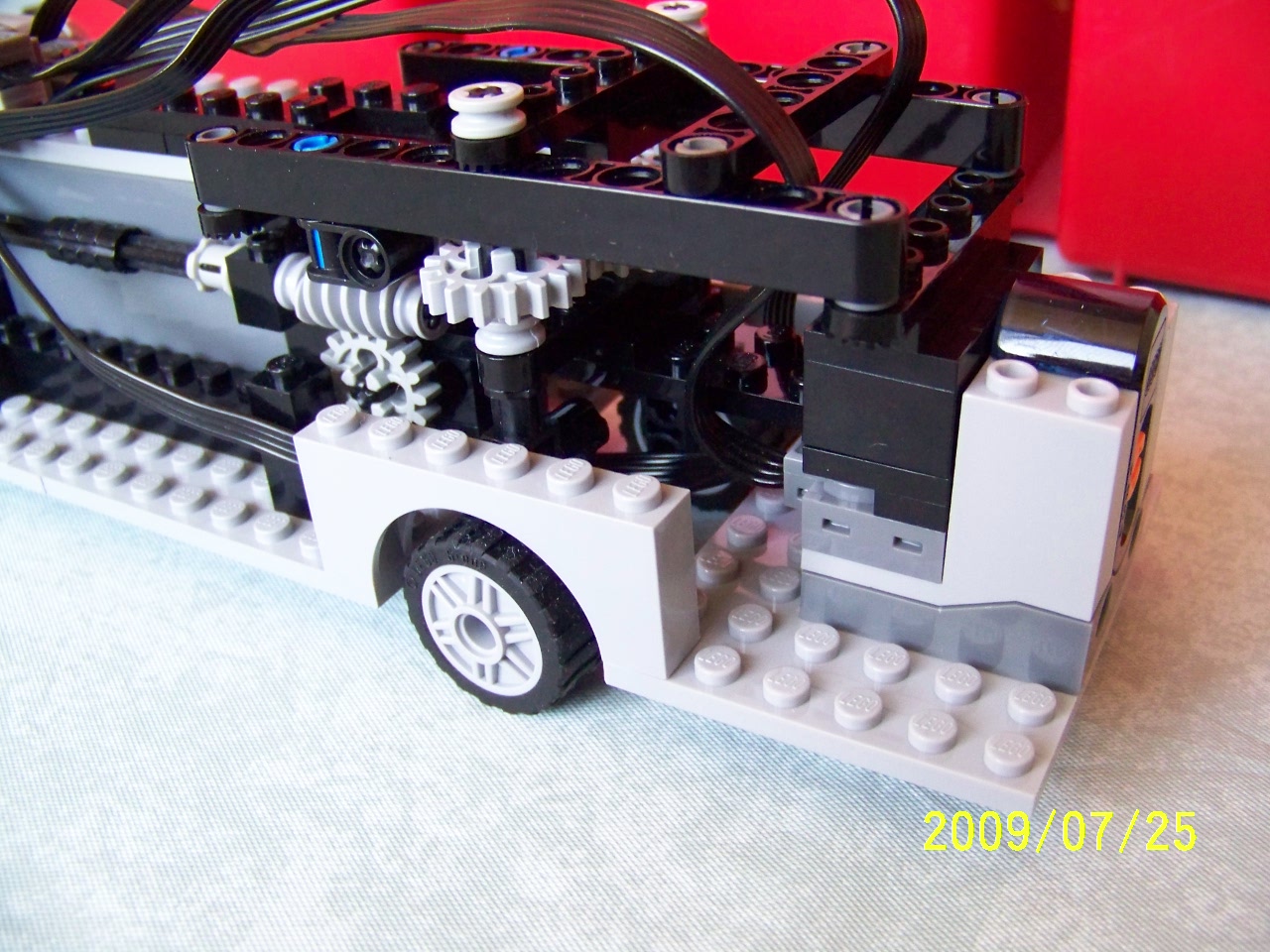
The second version of the steering system uses two worm gears, and replaced some simple bricks with Technic beams to hold gears. The front support also eventually changed to including the IR receiver as a structural element, since there was nowhere else to put it. Part of the challenge of the steering is that both front wheels need to be steered. The usual rack-and-pinion mechanism wouldn't work, because it moves the wheels, rather than just turning them in place. So, I went with directly gearing the wheels to make them steer.
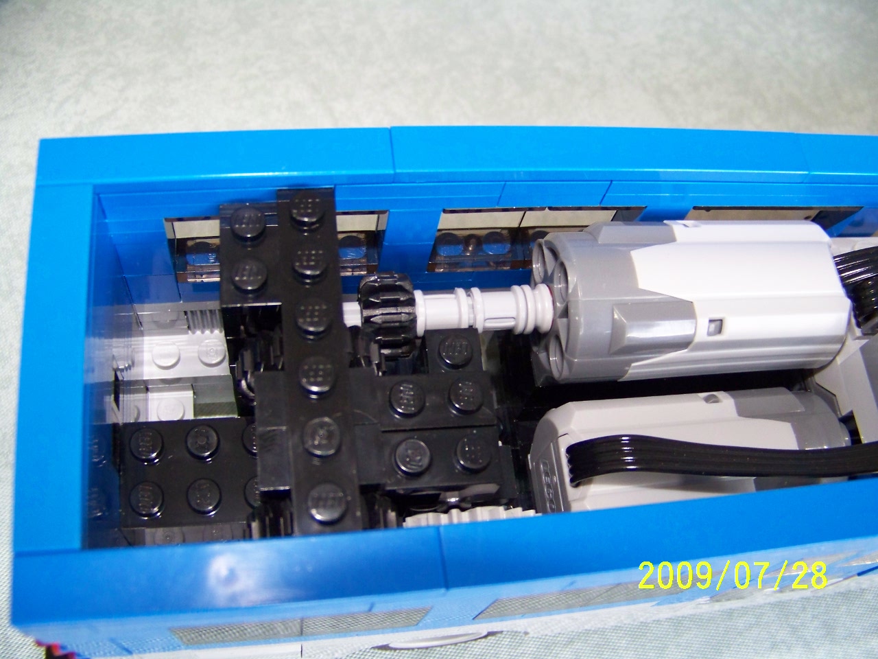
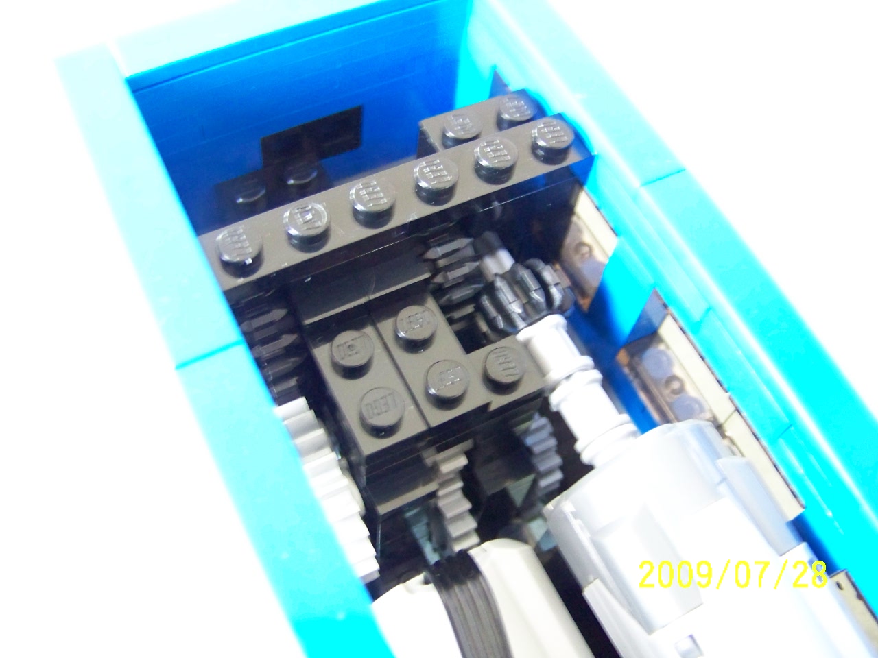
To get the directions correct, there needs to be an odd number of gears between the two vertical steering axles. That was a problem with the space available. The end result is a fairly non-standard part use. A jumper plate is pressed upside down into the top of a 6-hole half-height lift-arm, and a 2-stud axle is inserted into the space between the center mould cylinder and the end of the upside-down jumper plate. The upper end of that 2-stud axle is similarly inserted into that space in a regular 1x2 plate attached to a jumper plate. The first picture under "Steering details" shows the upper plates. The choice between the 1/2 height lift-arms and the 1/3 height old-style levers is important to get the spacing right.
The above system got a decent speed on the steering, but needed more modifications to prevent gear jumping on the lower worm gear. None of the pictures show that, but I did manage to fit it in, holding the front of the long axle (now one stud longer) down.
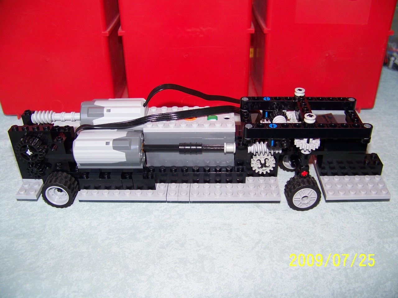
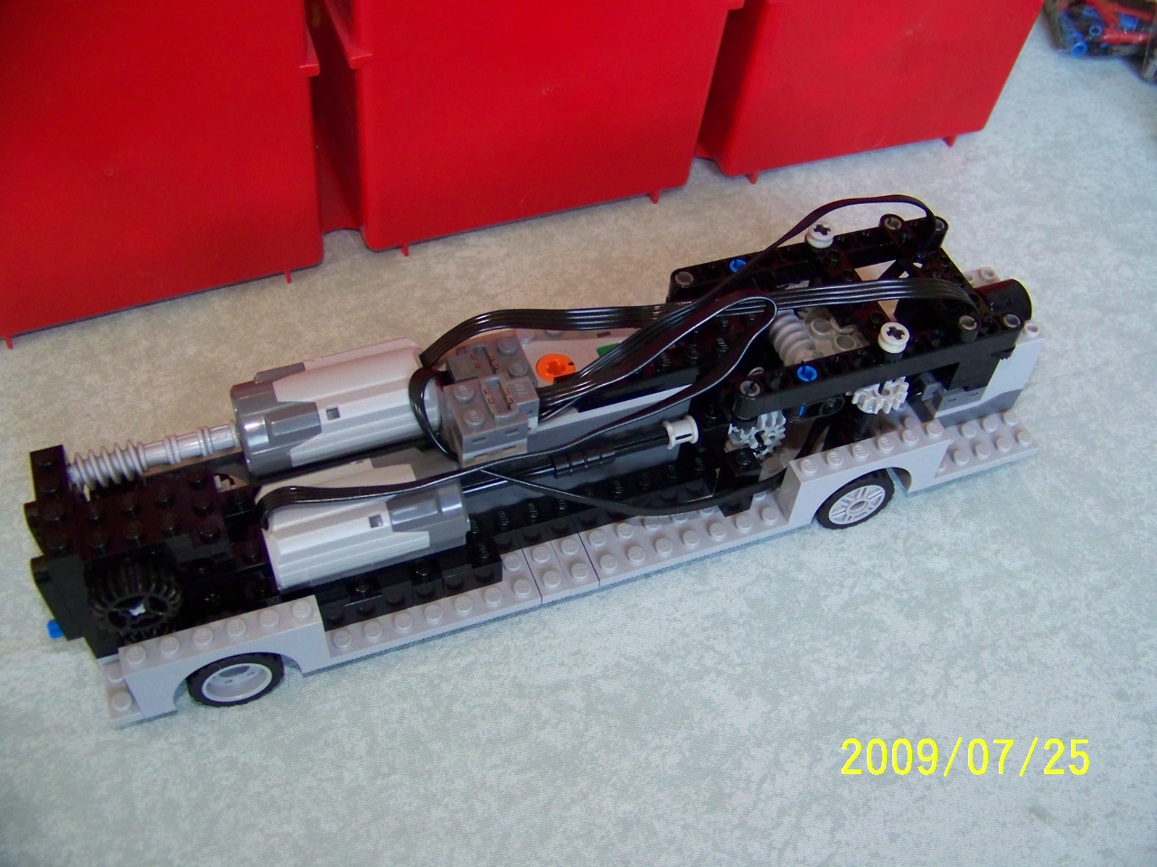
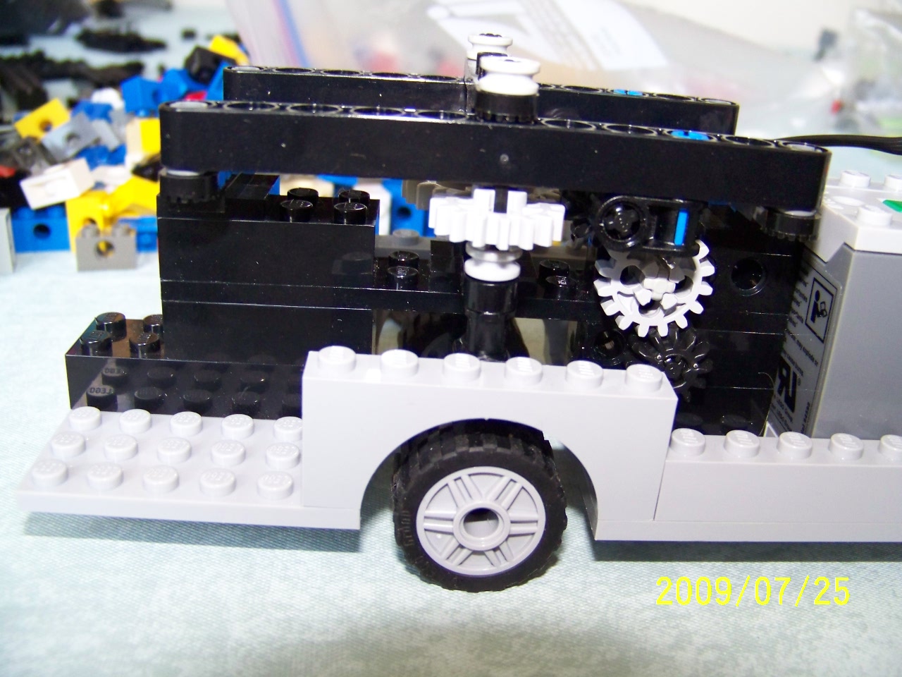
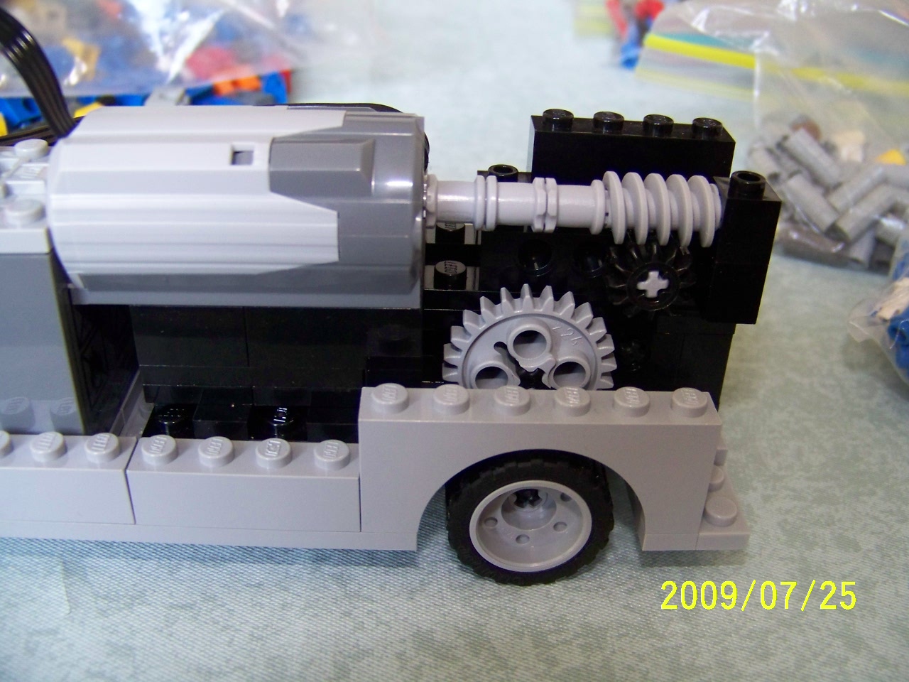
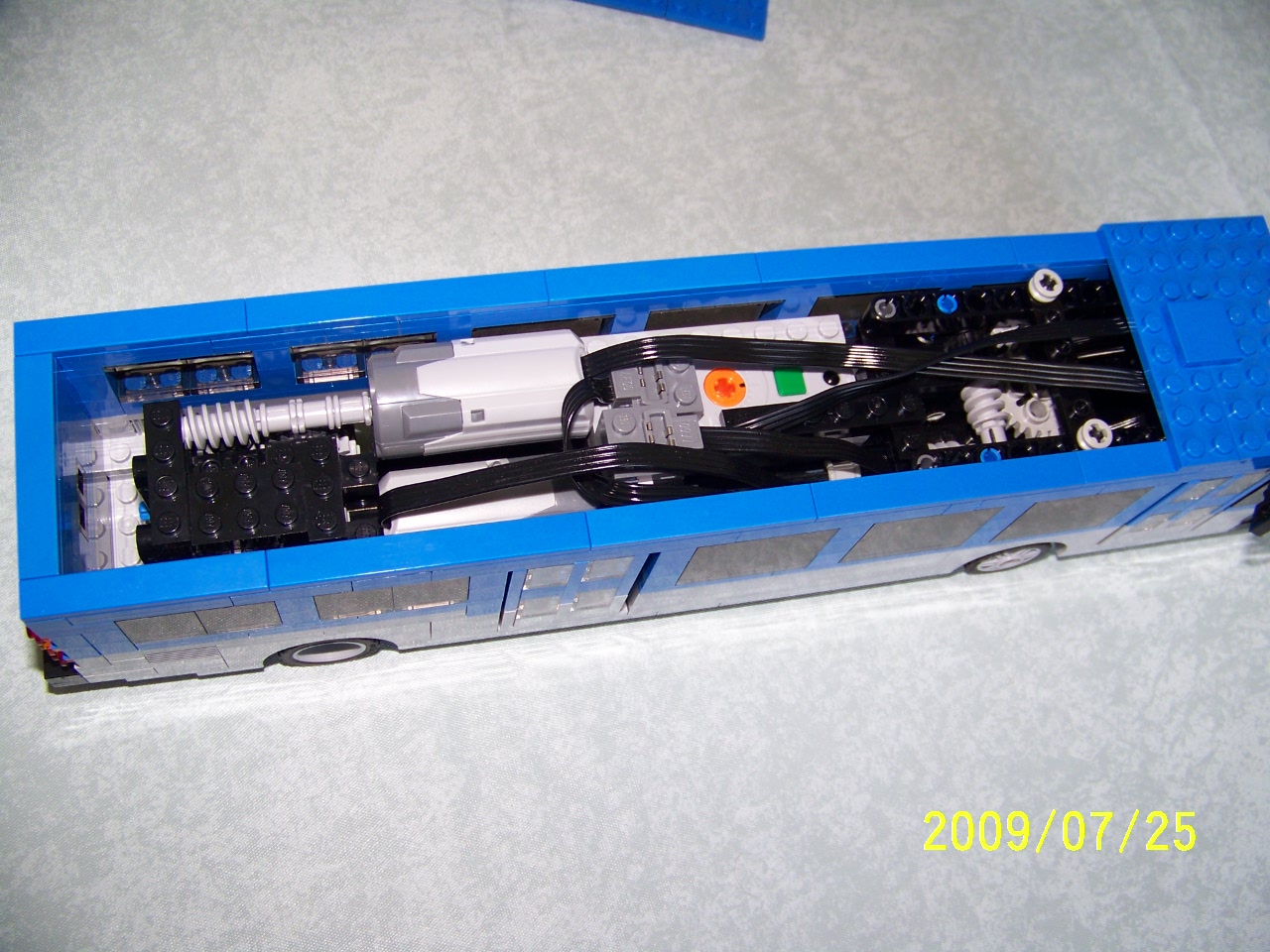
The bus speed needed increasing, however. Most of the pictures show the second version of that gearing. The right-hand side of that system can be adjusted for 5 different gear ratios, depending on which pair of gears is used. All of the ratios, however, suffer from being a speed increasing system off of the axle driven from the worm gear. They result in the bus "pulsing" as it moves, which is quite annoying. Also, that system appears to put quite a bit of load on the motor.
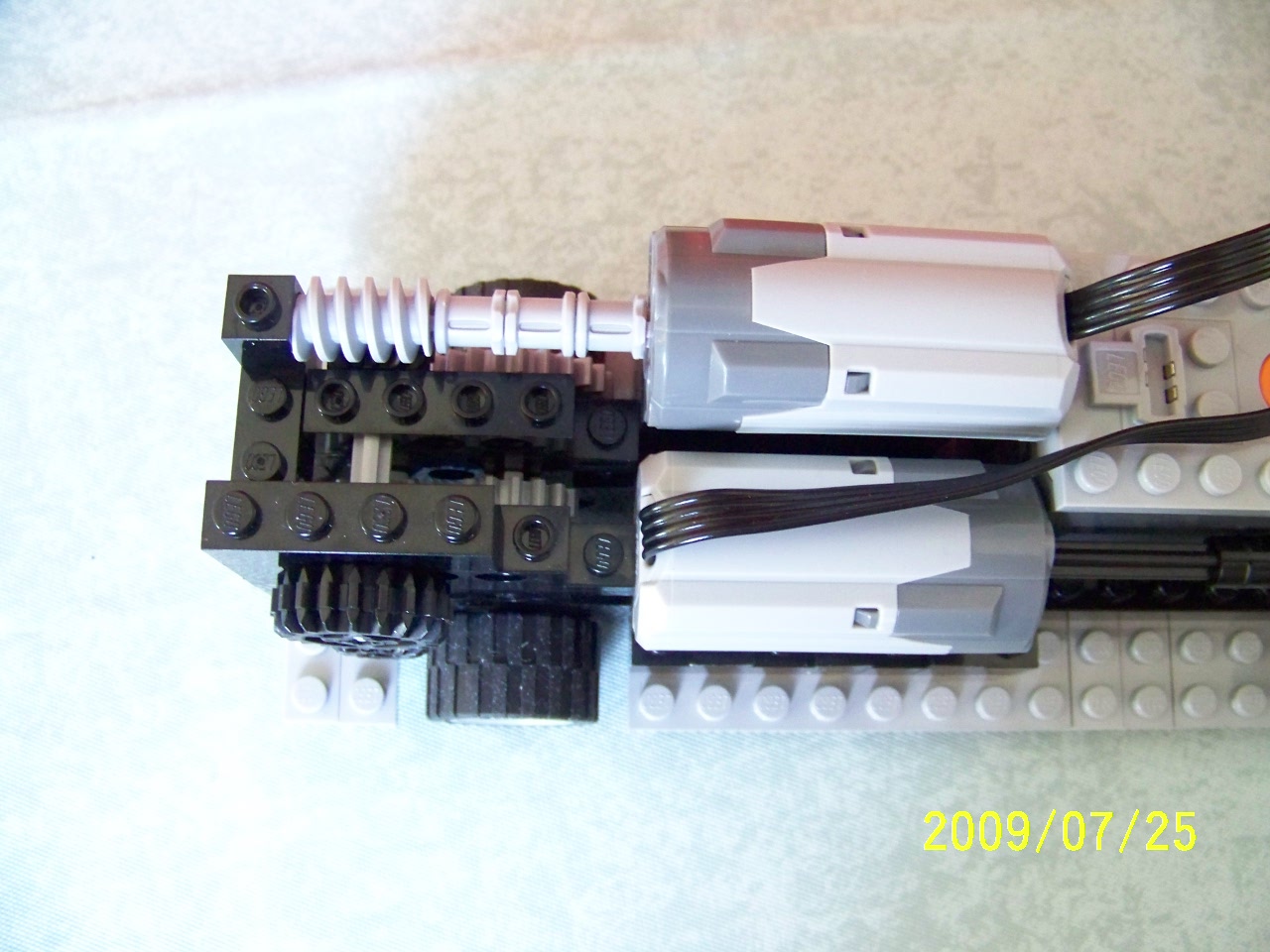
The final version of the rear gearing gets rid of the worm gear, replacing it with a pair of "fat" gears to achieve the right-angle change in axle direction. This system results in a slow bus, but not as slow as the original system. It also runs smoothly, and without any pulsing. In the movies, you can see the bus jiggling a bit as it moves - I believe that is the tire treads on the hard surfaces.
A short Power Functions extension cable was needed to go from the steering motor to the IR receiver - the cable connectors are attached to the top of the battery box, as are some of the parts used to hold the steering mechanism firmly down.
|
|
|
|
|
|
|
|
|
|
|
|
|
|
|
|
|
|
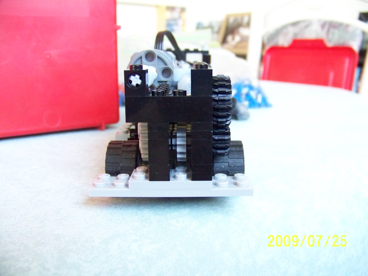
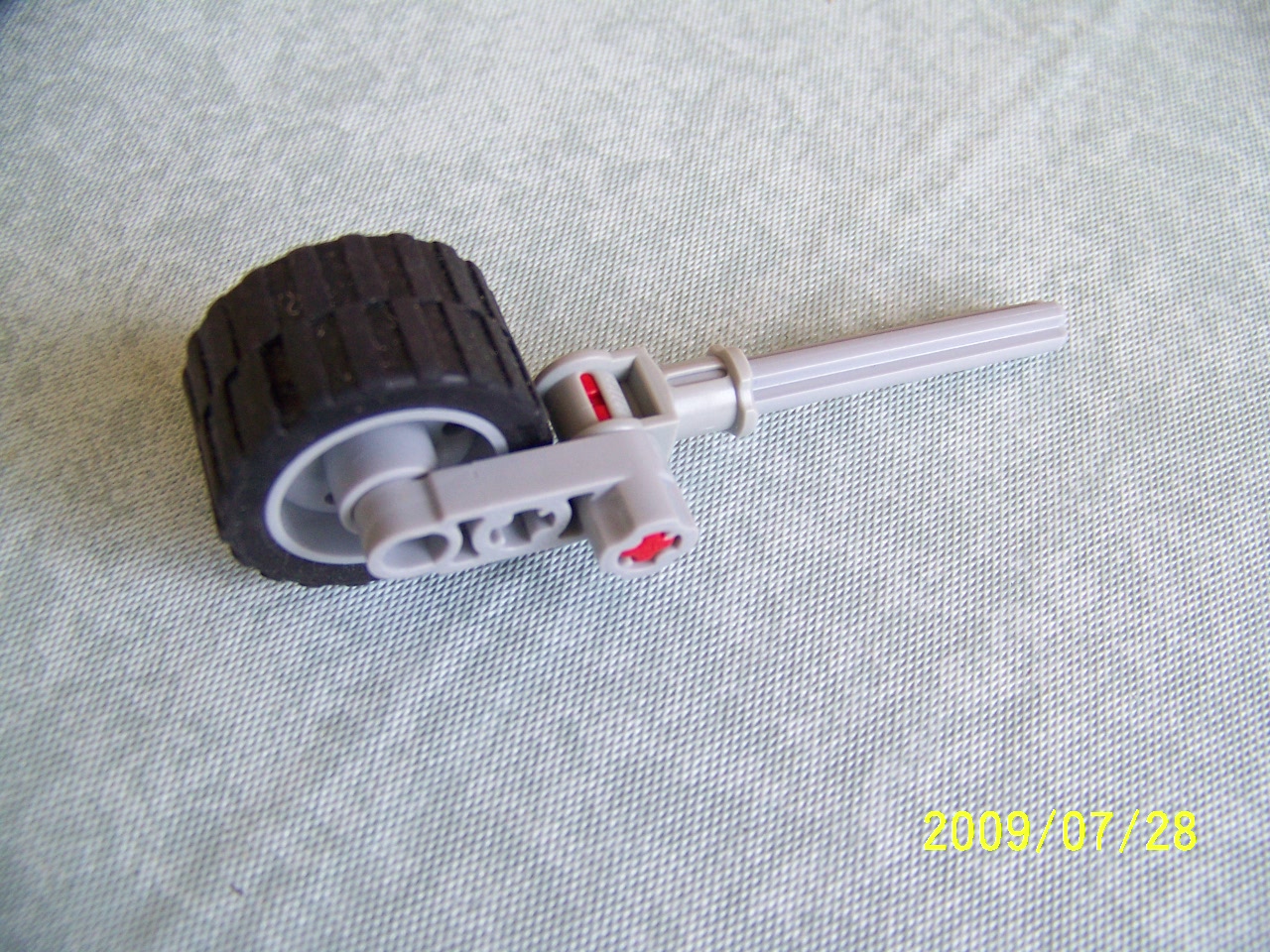
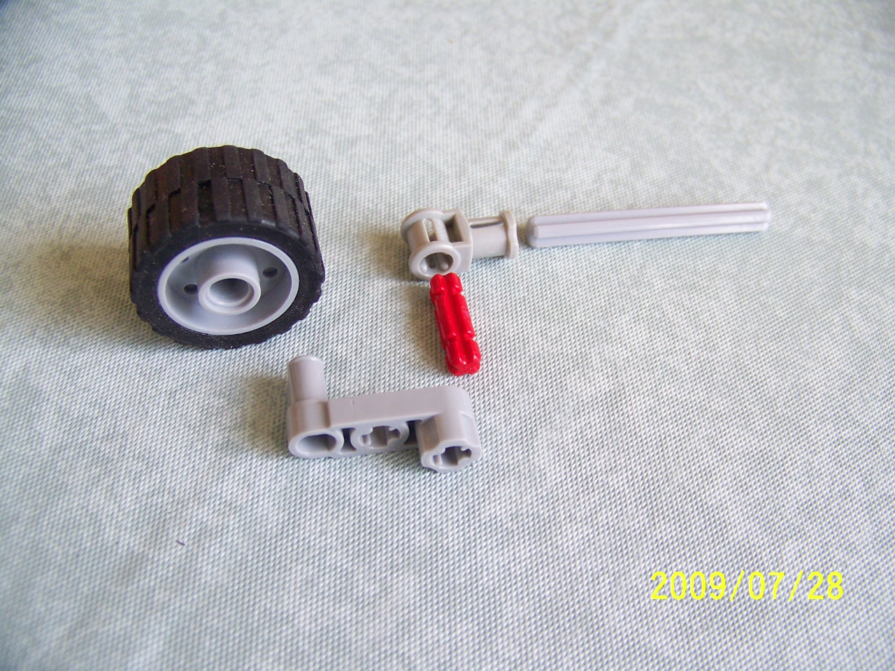
Before I noticed the crank pieces that I had, I had built this mechanism from smaller parts. However, the tan or grey axle/pins provide a fairly loose fit for the wheel, and it sags enough to rub noticeably on the piece above the wheel. A blue axle/pin makes a firmer grip, but provides a lot of friction which affects the bus motion. The crank pieces work much better.
|
|
The first video shows the bus on my kitchen floor. The bus will drive fine on my carpet, but the carpet absorbs the IR signal from the controller, so it is harder to demonstrate the bus there, since I keep losing control. Reflections from the kitchen floor (and appliances, etc.) provide for surer control.
Last night I took the bus to where we are building our layout for our next train show and tried it out on the town streets there. The roadplates and baseplates do not reflect the IR light as much as my kitchen floor does, so control of the bus is poor. Also, the roadplates do not provide much traction, so the bus can barely move over studs, and when the front wheels hit something like a plate holding baseplates together, they can't go any further. In once instance, the tail end of the bus slid around as the wheels slipped on the roadplate. I took a quick look at raising the IR receiver so that its dome sticks out the top of the bus, but that won't work without raising the whole top of the receiver out of the bus, due to the structural use of the receiver as the front support for the steering mechanism. Oh well, the bus is a nice toy anyway.
NALUG Member Ian took my powered bus home for a few months. He mounted the IR receiver at the back, with the sensor sticking out of the roof. He also changed the steering mechanism to a self-centering system using springs. All much better - thanks Ian!